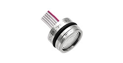
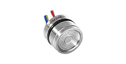
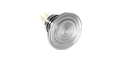
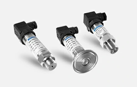
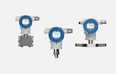


Pressure Transmitter for Oxygen Measurement
Widely used in the medical and pharmaceutical industry for oxygen measurement
All-welded design
Fully digital temperature compensation calibration
Adapted to breathable membranes
New Product Change Notice (PCN) effective Jan 1, 2025. MICROSENSOR appreciate your understanding.

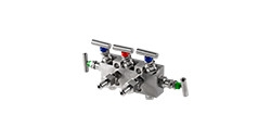
MV7000
The actuation of opening, closing, balancing, and venting operations of differential pressure transmitters and pressure transmitters
Leave a MessageMV7000
Used For
The actuation of opening, closing, balancing, and venting operations of differential pressure transmitters and pressure transmitters
Leave a MessageIntroduction
Valve manifolds are devices utilized for the actuation of opening, closing, balancing, and venting operations of differential pressure transmitters and pressure transmitters, controlling specifications such as fluid pressure, flow, and temperature. MV7000 series valve manifolds consists of shut-off valve, two-valve manifold (column), two-valve manifold, three-valve manifold, and five-valve manifold configurations.
Functions
• Shut-off valve (Code: N)
The function of the shut-off valve is to open or shut off the pipeline flow. During installation, it is crucial to ensure that the flow direction of the applicable medium aligns with the arrow direction marked on the valve body.
• Column two-valve manifold (Code: M)
The column two-valve manifold consists of a shut-off valve (for opening, closing or purging) and a vent valve (typically for debris, water, or air). It is crucial to ensure that the flow direction of the applicable medium aligns with the arrow direction marked on the valve body. The shut-off valve and the vent valve are are distributed at 180°.
• Two-valve manifold (Code: 2)
The column two-valve manifold consists of a shut-off valve (for opening, closing or purging) and a vent valve (typically for debris, water, or air). It is crucial to ensure that the flow direction of the applicable medium aligns with the arrow direction marked on the valve body. The shut-off valve and the vent valve are are distributed at 90°.
• Three-valve manifold (Code: 3)
The three-valve manifold consists of a valve body, two shut-off valves, and a balance valve. Based on the function of each valve in the system, it can be categorized as follows: the positive (upstream) globe valve, the negative (downstream) shut-off valve, and the balance valve located in between. The three-valve manifold is used in conjunction with a differential pressure transmitter to establish or isolate communication between the positive and negative pressure measuring chambers and the impulse point, or to isolate or establish communication between the positive and negative pressure measuring chambers.
• Five-valve manifold (Code: 5)
The five-valve manifold is essentially a three-valve manifold with the addition of vent valves on both the high and low-pressure sides.
Image:
Introduction
Valve manifolds are devices utilized for the actuation of opening, closing, balancing, and venting operations of differential pressure transmitters and pressure transmitters, controlling specifications such as fluid pressure, flow, and temperature. MV7000 series valve manifolds consists of shut-off valve, two-valve manifold (column), two-valve manifold, three-valve manifold, and five-valve manifold configurations.
Functions
• Shut-off valve (Code: N)
The function of the shut-off valve is to open or shut off the pipeline flow. During installation, it is crucial to ensure that the flow direction of the applicable medium aligns with the arrow direction marked on the valve body.
• Column two-valve manifold (Code: M)
The column two-valve manifold consists of a shut-off valve (for opening, closing or purging) and a vent valve (typically for debris, water, or air). It is crucial to ensure that the flow direction of the applicable medium aligns with the arrow direction marked on the valve body. The shut-off valve and the vent valve are are distributed at 180°.
• Two-valve manifold (Code: 2)
The column two-valve manifold consists of a shut-off valve (for opening, closing or purging) and a vent valve (typically for debris, water, or air). It is crucial to ensure that the flow direction of the applicable medium aligns with the arrow direction marked on the valve body. The shut-off valve and the vent valve are are distributed at 90°.
• Three-valve manifold (Code: 3)
The three-valve manifold consists of a valve body, two shut-off valves, and a balance valve. Based on the function of each valve in the system, it can be categorized as follows: the positive (upstream) globe valve, the negative (downstream) shut-off valve, and the balance valve located in between. The three-valve manifold is used in conjunction with a differential pressure transmitter to establish or isolate communication between the positive and negative pressure measuring chambers and the impulse point, or to isolate or establish communication between the positive and negative pressure measuring chambers.
• Five-valve manifold (Code: 5)
The five-valve manifold is essentially a three-valve manifold with the addition of vent valves on both the high and low-pressure sides.


Widely used in the medical and pharmaceutical industry for oxygen measurement
All-welded design
Fully digital temperature compensation calibration
Adapted to breathable membranes

Standard I²C or SPI protocol
Low power consumption with temperature compensation
RoHS approved


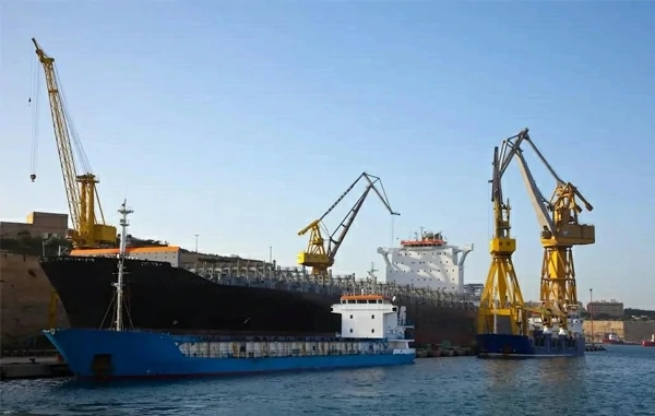
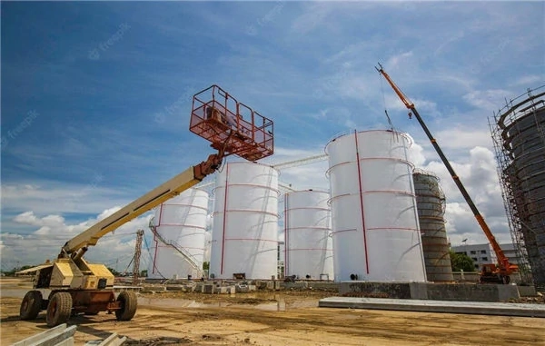
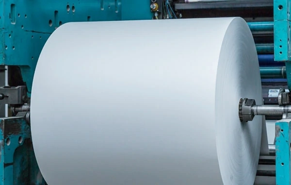
In the paper industry, the alkali recovery system is an essential part that operates under harsh conditions. The system needs strong pressure, temperature, and flow instrumentation to handle high temperatures, high pressures, and corrosive media.
more info...
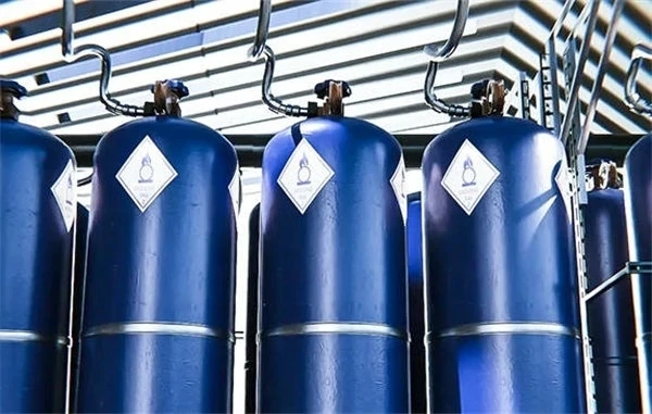
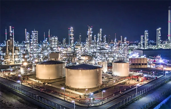
The production of positive and negative electrode materials for lithium cell requires the transmission of powdered materials. The sealed pipelines realize pneumatic transmission of solid powder or particles. However, blockages can occur in the container when conveying materials with large particle sizes, high viscosity, or poor flow ability. Installed pressure transmitters solve this problem. An abnormal pressure alarm will be triggered to identify the location. This facilitates timely repair of the blockage, ensuring normal production and operation.
more info...
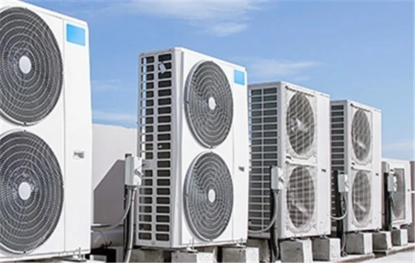
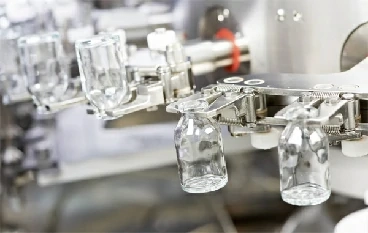
Before beer bottles, medicine bottles, and condiment bottles are filled with liquid, they need to be cleaned first. The cleaning process is as follows: First, the bottles are filled with lye in the alkali tank to remove most of the stains; then, the bottles are back washed with high pressure using water of different temperatures to wash away the remaining impurities and lye. To ensure the stable operation of the bottle washing machine, the level of the alkali tank needs to be measured by hydrostatic pressure. In addition, the pressure of the alkali tank water inlet pipe and the nozzle pipe also needs to be measured.
more info...
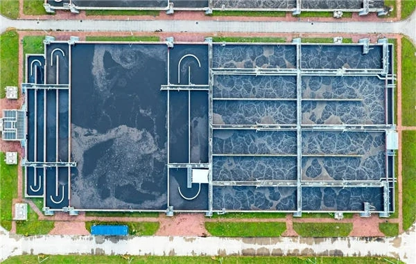
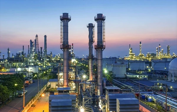
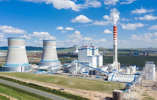
Pressure, flow, and level measuring instruments are deployed in water tanks, pipelines, and water inlets/outlets. This helps to manage the macro-control of production data in the water plant. Measuring instruments ensure smooth operation and normal production.
more info... Copyright © 2026 MICRO SENSOR CO., LTD


