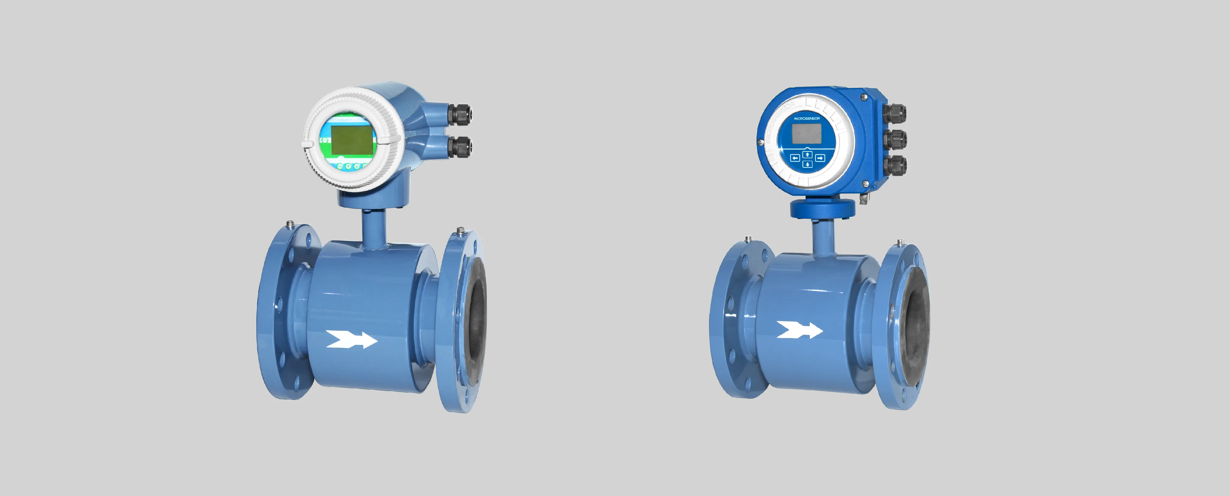
Electromagnetic flowmeter is widely used for industrial sewage treatment, water supply, and drainage in Chemical plants, municipal pipeline networks, and farms, etc.
Problem Description:
The flowmeter is installed on a vertical pipeline. When the water pump is turned on, the electromagnetic flowmeterworks normally and when the pump is turned off, the liquid flows back in the pipeline (the check valve is not installed).
After the liquid has flowed back for a while, the data value of the electromagnetic flowmeter has both positive and negative, causing an error on the site water consumption.
Problem Analysis:
Because no check valve is installed in the vertical pipeline, a complete water use process in the pipeline is as follows:
Empty pipeline --- Turn on the pump (the liquid fills the pipe) --- Normal flow measurement --- Turn off the pump --- water flows back in pipes
The system is just like picture 1 below:
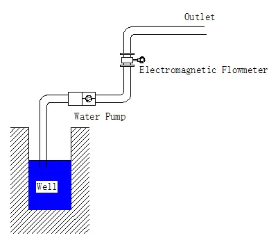
Picture 1
When the water pump is turned on and the system is running normally, the situation in the pipeline is shown in Picture 2 (blue in the figure represents liquid).
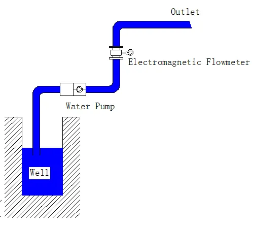
Picture 2
After the water pump is turned off, and the water in the pipeline flows back. When the water has returned, the situation in the pipeline is shown in Figure 3. In Figure 3, the blue on both sides of the electromagnetic flowmeter represents the liquid, most of the liquid in the pipeline returns to the well, but part of the liquid remains on the wall of the pipeline. Similarly, part of the liquid will also remain on the lining of the electromagnetic flowmeter.
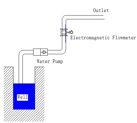
Figure 3
The liquid remaining on the pipe wall and the lining of the electromagnetic flowmeter will gradually form small water droplets. When the water droplets move downwards due to gravity, an instantaneous flow will be formed on the flowmeter. This flow value may be positive or negative. Just like figure 4, the red represents water droplets here.
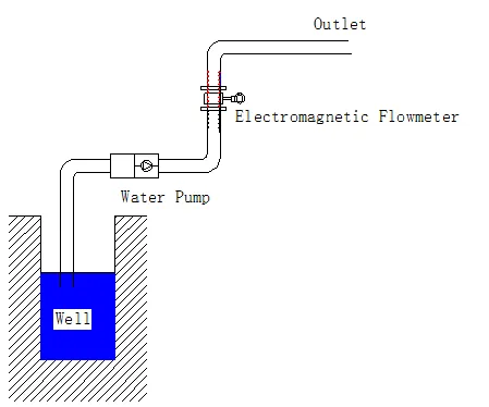
Figure 4
Solution:
1. Install a check valve in the front section of the electromagnetic flowmeter to prevent the occurrence of such working conditions.
2. Based on that, the electromagnetic flowmeter has set corresponding function items on the menu to specifically solve this problem. The solution steps are as follows:
(1) Observe the resistance value displayed by the electromagnetic flowmeter converter when the pipeline is full.
(2) Observe the resistance value when there is no water in the pipeline, but the electromagnetic flowmeter has a flow display (that is, the resistance value when a problem occurs).
(3) Set the "empty tube alarm threshold” in the menu item to a resistance value smaller than that in step (2).
For example:
(1) When the electromagnetic flowmeter in the pipeline is full, the resistance value is 0.2KΩ.
(2) After the pump is turned off, the resistance type is 2.1KΩ when the flow data fluctuates.
(3) Set the "empty pipe alarm threshold" to 1.5KΩ.
The specific method of flow measuring with electromagnetic flowmeters differs according to different actual conditions. Feel free to contact us via sales@microsensor.cn with a unique requirement. Our technical team will provide you with the best product solutions according to the field environment. Our company has a standard technical system, strong technical support, and a complete industrial supply chain to provide you with comprehensive customized services.
Previous posts:MFE600E Electromagnetic Flowmeter Applied in Reclaimed Water Treatment
Next chapter :Basic Knowledge of Pressure Sensors Applications








 Copyright © 2025 MICRO SENSOR CO., LTD