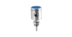
The common output signals of pressure transmitters include 4-20mA, 0-5/10V DC, 0.5-4.5V DC, RS485-Modbus, I²C, PF-bus ,etc. According to the transmission mode of power and signal, it can be divided into two-wire system, three-wire system and four-wire system;
The two-wire system means that only two wires are used for the electrical connection between the field transmitter and the control room instrument. These two wires are both the power wire and the signal wire. The two-wire transmitter is not easily affected by parasitic thermocouples and resistance voltage drop and temperature drift along the wires. Very cheap and thinner wires can be used, which can save a lot of cables and installation costs.
The three-wire system means that the field transmitter and the control room instrument use three wires, a positive power wire, and two signal wires, one of which is a common ground.
The four-wire system refers to the four wires, two power wires, and two signal wires used for the connection between the field transmitter and the control room instrument.
When the output resistance of the current source is large enough, the voltage induced by the magnetic field coupling into the loop of the wire will not have a significant impact, because the current caused by the interference source is very small, and the interference can generally be reduced by using a twisted pair; two-wire system and the three-wire system must use shielded wire, and the shielding layer of the shielded wire must be properly grounded.
Capacitive interference will cause errors related to the receiver resistance. For a 4-20mA two-wire loop, the receiver resistance is usually 250Ω (sampling Uout=1~5V). This resistance is small enough to cause significant errors. Therefore, it can be allowed that the wire length is longer and farther than the voltage telemetry system.
Each single display and reading device or recording device can be switched between different channels with unequal wire lengths, without the difference in accuracy due to unequal wire lengths, realizing decentralized collection and achieving centralized control.
Using 4mA for zero level makes it very convenient to judge open circuit and short circuit or sensor damage (0mA state), and it is very easy to add one or two lightning protection and surge protection devices to the two-wire output port, which is beneficial to safety, lightning protection and explosion protection.
Pressure transmitters can also be divided into analog output and digital output according to the output mode:
The common ways of analog output are: 4-20mA, 0-5/10V DC, 0.5-4.5V DC, 0.5V~2.5V DC
The common ways of digital output are: RS485-Modbus, I²C, with higher precision, but at the same time the product response is slow.
That's all for today's tips on pressure transmitters. See you next time!







 Copyright © 2025 MICRO SENSOR CO., LTD


