Onsite Inspection
For a Yellow River Diversion Project, the monitoring point is installed in the field and unattended. It is necessary to conduct a survey and evaluation on the user's site to select suitable instruments and propose a transformation plan. The onsite inspection must include the following items:
1. The channel is a rectangular channel or a trapezoidal channel, otherwise, it needs to be transformed;
2. The location of the open channel flow meter should be ≥10D upstream and ≥5D downstream (D: channel width);
3. The bottom of the channel should be relatively flat and without siltation.

Open Channel Flowmeter Selection and Online Monitoring
After the onsite inspection, the flow area method to measure the flow of open channels is recommended for customers. The liquid level is measured by an ultrasonic level meter, and the flow rate is measured by an electromagnetic flow meter.
System Components
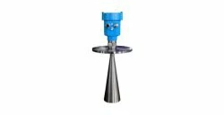
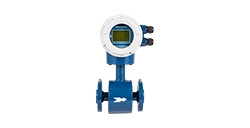
The open channel flowmeter consists of three parts: flow indicator, electromagnetic flow meter, and ultrasonic level transmitter. The electromagnetic flow meter is installed in the channel, and converts the water flow speed into an electrical signal and transmits it to the display through a cable. The ultrasonic level transmitter is installed above the channel near the flow meter, measures the depth of the water level above the cross-section of the channel, and transmits it to the display with a 4-20mA signal. The display instrument calculates the water flow rate of the cross-section through the flow velocity signal, water level signal, and various channel parameters.

System Features
According to the multi-point method of open channel flow measurement standards, the influence of flow velocity measurement errors caused by flow changes on flow can be randomly corrected.
In order to improve the measurement accuracy, the electromagnetic flow meter is applied to measure the channel flow velocity, the flow rate is calculated by the flow velocity and liquid level.
Wireless transmission
It adopts a solar power supply method and is equipped with an Earth1006 wireless communication remote monitoring terminalto realize multi-channel, multi-parameter physical quantity collection, and use a mobile public network to upload data to the cloud. This solution is suitable for monitoring the flow and liquid level of unattended monitoring points in a wide area in the wild.

Solar control system/ wireless remote monitoring terminal Earth1006
The monitoring point is both lightning-proof and waterproof. The battery and solar power supply can solve various on-site power supply problems. The operator can query the data through the computer or mobile phone to monitor the changes of the liquid level and flow in real-time. The mobile phone monitoring is shown in the figure:

(Cumulative and instantaneous flow)
Onsite Installation

(1 flow indicator, 2 ultrasonic liquid level transmitter 3 flow meter, H level)
1. Flowmeter installation
Choose a relatively straight section of the channel or river, and try to avoid gates, curves, water inlets/outlets, and up and down slopes. The straight channel section must have a certain length, and the length of the upstream and downstream of the straight channel section is preferably greater than 10 times the channel width. The flow meter is installed on the sidewall of the channel (if there is no problem of sedimentation, it can be installed at the bottom of the channel). The vertical depth position is not buried by the mud and can ensure normal measurement. The direction indicator points downstream of the water flow, ensuring that the flow meter is parallel to the water flow axis.
2. Level transmitter installation
The ultrasonic level transmitter should be applied as close as possible to the installation position of the electromagnetic flowmeter. It shall be perpendicular to the water surface. The distance from the port plane of the ultrasonic level transmitter to the bottom of the channel is 5-10cm larger than its actual range. Waveguides should be installed if thereis litter, refuse, air bubbles, or large fluctuations in the water. The diameter of the waveguide should be greater than 120mm and there should be no joints.

(The project site is installed by one-point multi-line multi-point method)
The implementation of the monitoring solutions in more complex environments needs to refer to actual conditions. Our technical team will provide you with the best product solutions according to the field environment. Just contact us or leave messages.
Previous Posts: Sewage Treatment Application with Electromagnetic Flow Meter
Next Chapter: Pressure Transmitters for Environmental Protection








 Copyright © 2025 MICRO SENSOR CO., LTD